Have you ever sat down and wondered to yourself, “How does a hydraulic press work?” We actually think about it all the time here at Atlantic Hydraulic Systems. 

The fundamentals of a hydraulic press were actually made possible because of a French philosopher named Blaise Pascal. In fact, Pascal theorized and developed what we now know as Pascal’s Law.

In this article, we’ll delve into Pascal’s Law, the mechanics of hydraulic presses, exploring the force exerted, pressure applied, and the fascinating principles that make them tick.

What Is Pascal’s Law? 

A change in pressure at any point in an enclosed incompressible fluid at rest is transmitted equally and undiminished to all points in all directions throughout the fluid and acts at a right angle to the enclosing walls.

How Does A Hydraulic Press Work?

Hydraulic presses harness the hydraulic principle, a concept grounded in Pascal’s Law, to perform various tasks. This hydraulic principle dictates that any pressure applied to an incompressible fluid within an enclosed system will be transmitted uniformly in all directions.

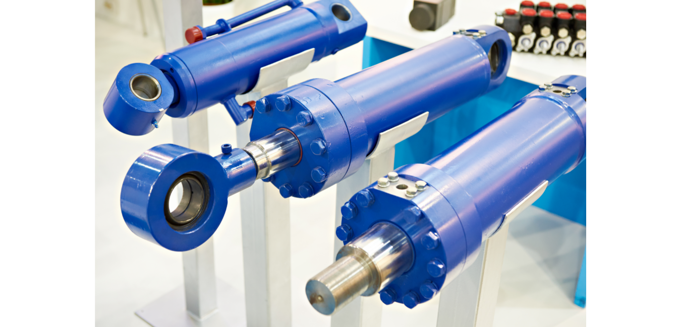
In a hydraulic press, there are two interconnected cylinders: a larger cylinder and a smaller cylinder. High-pressure hydraulic oil is supplied to the larger cylinder, creating an increase in pressure. As per Pascal’s Law, this increase in pressure is transmitted undiminished throughout the fluid. Consequently, it exerts a substantial amount of force on the piston within the larger cylinder.

This force is then leveraged to extend the larger cylinder, which in turn exerts pressure on the object being pressed. The mechanical force applied to the smaller cylinder is multiplied many times over, resulting in a force exerted on the object that is significantly greater than the initial force applied to the hydraulic system.

Check Out Our Collection Of Hydraulic Power Units!

This process is a direct application of Pascal’s Law. The law states that the pressure applied to any part of the enclosed liquid will be transmitted equally in all directions through the liquid.

You may have already seen the damaging effects of a hydraulic press on everyday household items in YouTube videos. Still, a hydraulic press is even strong enough to flatten a solid natural diamond in an instant!

Why Use Hydraulic Presses?

The application of hydraulic systems in presses includes various benefits, making them a preferred choice over mechanical alternatives:

  • Cost-Effective: Hydraulic presses are a cost-effective solution for a wide range of tasks.
  • Durability: They are known for their durability and minimal breakdowns.
  • Precise Control: Hydraulic systems offer precise control over the amount of force exerted and the speed of operation.
  • Noise Reduction: Hydraulic presses operate more quietly than their mechanical counterparts.
  • Power Amplification: These systems can efficiently convert a small input of power into a substantial force output, illustrating the power of Pascal’s Law.

In addition to their use in presses, hydraulic systems find applications in various fields, including hydraulic brakes and numerous industrial processes. The capacity to harness the hydraulic principle and Pascal’s Law in hydraulic presses demonstrates the remarkable efficiency of incompressible fluids in transmitting force and pressure.

Understanding how a hydraulic press works involves appreciating the fundamental hydraulic principle governed by Pascal’s Law. This principle allows hydraulic systems to magnify mechanical force many times over, making them indispensable in various industries and applications.

You’ll find our experts happy to answer any questions you have about hydraulic fluids and presses!

Ever since the Industrial Revolution, hydraulic systems have become an integral part of our everyday lives. Hydraulic systems use liquids, usually oils, as their working fluids. These liquids are stored in a closed system and pumped to where they are needed when pressure is applied.

Why Liquids Are Well Suited For Hydraulics

A hydraulic machine is a device that uses liquid fluid power, such as water or oil, to perform work. Heavy construction vehicles are a typical example of hydraulic machines.

Hydraulic systems are confined pressurized systems that use and store liquids and this is an advantage over pneumatic units as the hydraulic fluid itself is not very compressible so doesn’t suffer from delays in movement, unlike a gas-based pneumatic system which needs a compressor to compensate for this task.

Check Out Our Collection Of Hydraulic Power Units!

In this machine, the liquid fluid, oil in most cases, is pumped to various motors and cylinders throughout the vehicle, which becomes pressurized according to the resistance present.

-Liquids are basically incompressible thus leading to tight control of cylinder or hydraulic motor movement and positioning.
-Small and flexible tubes, hoses, and pipes can move a lot of power over long distances and around sharp bends.
-Liquid fluids can be safely pumped to higher pressures than gasses thus transmitting more power than gasses.
-Hydraulic force can be multiplied easily without mechanical gears and with little concern for the distance between mechanically driven objects.
-Liquids (hydraulic oil) provide lubrication to rotating equipment such as hydraulic pumps.
-Liquids (hydraulic oil) provide rust and corrosion protection to hydraulic components.

Conclusion

Learning how liquids work in hydraulic systems is an essential first step to understanding the benefits of using them. In addition, we have helped many customers design and build their custom oil-based hydraulic systems, so we know that they can be a massive asset to your business!

If you want help designing or maintaining a system like this, give us a call. You’ll find our engineers happy to answer any questions about hydraulic fluids and fluid dynamics or anything else related to hydraulics engineering.

In these days of increasing energy costs as well as the push to lower our carbon footprint, there are some simple ways to design a hydraulic system that consumes less energy.

This blog will cover several key areas to consider in the design of an efficient hydraulic power unit. You will learn how all of these parts come together to make a complex and energy-efficient system.

Correct Hydraulic Pump Specification

When the hydraulic pump is specified for an application, it should be sized close to the system flow requirements unless flow upside possibilities are required for the system.

Pump Style Selection

The two basic hydraulic pump types are fixed and variable displacement.

The fixed displacement pump will always produce flow based on the motor speed and the pump’s displacement. If the system is idle but still running, the fixed displacement pump will produce flow and push oil over the relief valve using energy.

It is common to “dump” this oil back to the tank freely using an unloading valve or a directional valve with an open center. Another option is to lower the pressure during idle times with a 2-pressure relief valve or proportional relief valve. Fixed displacement pumps are often preferred for low usage applications where the unit is not running all day.

The variable displacement pump will only produce flow when the outlet pressure is less than the set pressure for the pump. Once the pump pressure is reached the pump goes into “neutral” automatically and waits for the pressure to drop to produce flow again.

The pressure often drops when a valve is opened to move a cylinder or hydraulic motor. These types of pumps still use energy even when spinning in neutral. Lowering this deadhead pressure during idle times will decrease energy usage. Variable displacement pumps generally use less energy than fixed displacements pumps.

Use of Inverter Drives

A good device to consider if you want to make your power unit more efficient, as it allows you to adjust the output speed of the unit’s motor and pump; some modern drives can make units 50% more energy efficient while also reducing noise levels and environmental impact.

System piping

In the design stage of a power unit and its installation, it is always best to try to minimize and bends in the system as this will allow the hydraulic fluid to flow more freely and efficiently. Pipe sizing is crucial to minimize pressure losses that add to the power requirements.

The Uses Of Hydraulic Power Systems

When deciding what kind of Hydraulic Power system that you will purchase it is best to look at your individual needs. What pressure and flow will you need? There are options ranging from up to 25HP to over 100HP to suit all situations.

Hydraulic power systems are used in everything from bridge building to general construction. At its simplest, you may have hydraulic power used firsthand in the form of a hand jack then from a 1500 HP diesel engine. From this example, it is easy to see how a low amount of force can be spread out to accomplish much more work.

A full hydraulic system often includes an accumulator, hydraulic cylinder, control valves, heat-exchanger, relief valve, pump, filter, and reservoir.

Safety

It is important to remember that Hydraulic systems are heavy pieces of machinery and therefore require specific training to properly use them. There are training courses available to certify any of your personnel who might be using this system.

The biggest mistake people make is thinking that because it is just fluid that it is not dangerous. When in fact the fluid itself can be incredibly dangerous causing serious burning.

Furthermore, even though these systems are small they can produce a lot of force. Make sure that if you are looking into hydraulic systems that you fully understand the safety measures required to maintain them.

Phosphate Ester fluids are not easy on hydraulic components, especially when there is degradation in the fluid. There is a point in the life of an EHC hydraulic power unit where the returns of replacing the HPU outweigh the replacement component, maintenance, and downtime.

  • Replacement EHC HPUs (Hydraulic Power Units) generally contain:
  • Redundant 60 HP motors
  • Redundant 4000 PSI 55 GPM pressure compensated piston pumps
  • Reservoir sizes from 100 – 1000 gallons
  • Duplex Pressure line filters and suction line filters
  • Reservoir Heaters
  • Heat Exchangers
  • Bladder style accumulators
  • Instrumentation such as Pressure transmitters, Oil Level transmitters, Temperature transmitters
  • Parker PVS Vacuum Dehydrator Phosphate Ester Oil Conditioning Unit: 5 – 20 GPM, 1-micron filtration, Water removal

Replacement systems are designed with component accessibility, redundancy, and system availability in mind. Most are custom designed to match your existing system with upgrades on any aspect required.

Atlantic’s engineers will specially design a system to provide redundant hydraulic oil flow and pressure to throttle valve spindle, shut down valves, and other control servo valves to control your turbine speed.

Call to speak to an engineer about your application (631) 234-3131

How do I prevent air from getting into my hydraulic oil?


Does it sound like there are marbles in your hydraulic pump? Does your cylinder keep creeping even after you have closed a valve to stop it?

All hydraulic fluid contains air. It is part of hydraulic oil’s makeup to contain up to 12% of dissolved air. Dissolved air in hydraulic oil is not problematic but “Free Air” or “Entrained Air” can cause serious issues. Outside of foaming of oil on the surface air can be present in three forms in hydraulic oil:

  • Dissolved Air – 6% to 12% of hydraulic oil is dissolved air by volume naturally.
  • Entrained Air – these are air bubbles usually 1mm or less spread throughout the oil
  • Free Air – is often a “pocket” of air trapped in part of the system such as a cylinder, hydraulic conductor or in a hydraulic pump.

Free air can usually be minimized by pre-filling and bleeding a hydraulic system prior to start-up. Entrained air occurs most often as a result of air making its way into a hydraulic system via the pump inlet. Leaks in suction lines or low reservoir oil level will allow free air to enter into the inlet of the pump. The free air will become entrained air as it exits the pump and the oil is compressed. Peak temperatures will develop and oxidation of the oil will occur. When these air bubbles pop, cavitation occurs and erosive wear increases significantly causing component damage.

Entrained air can also form from dissolved air when gaseous cavitation occurs. Common causes of this phenomenon are:

  • Clogged suction strainers or inlet filters
  • Turbulence on inlet side of pump
  • Too much lift required between pump inlet and reservoir oil level
  • Suction lines having too much restriction or being too small
  • Intake line being collapsed

Proper design, start-up and maintenance guidelines must be followed to prevent air contamination in a hydraulic system.

Bottom line is your hydraulic oil should not look like a milkshake or a well poured Guinness waiting to settle. Hydraulic oil should be relatively clear.

Fun engineering has always been a staple at Atlantic Industrial Technologies. We were honored to be selected to design, manufacture, install, and commission the hydraulics and controls for this Roof Raising endeavor. The 160,000-square-foot innovation, Science and Technology building at Florida Polytechnic University will be the cornerstone of the new campus in Lakeland, Florida. Less than 20 minutes from Orlando, the building was designed by Santiago Calatrava.

The hydraulic system along with our network of controls:

¨ Utilize 94 hydraulic cylinders to position 60 foot louvers

¨ Track the sun to provide optimal building shade throughout the day

¨ Use anemometer and lighting detection feedback to shut down roof ASAP

¨ Can control each louver individually to change the shape of the roof

Very simply….. the best way to have a cool running hydraulic system is to design it to draw the least energy possible to perform the required work. In other words, make it as efficient as possible.


Here are the 5 Best Ways to Keep Your Hydraulic System Cool in no particular order:

  1. Minimize system pressure when possible during idle periods: Often during machine cycles, there is a hydraulic dwell (idle) period where parts are loading, or the process may be heating or cooling. During this period of time, high-pressure pump flow is turned into heat as it spills over the relief valve. If a pressure-compensated pump is utilized, the pump’s leakage through the case drain creates greater heat at higher pressures than at lower pressure; often, a compensator dump valve can be utilized to lower pump pressure.
  2. Slow Electric Motor Speeds to Match Flow Demand: The advent of variable speed drives and inverter-duty electric motors provide a great way to “slow your hydraulic system down”  during non-peak use periods, especially while using fixed displacement pumps. Torque- speed curves of the drive/motor combination must be studied due to the fact that torque will drop off at lower speeds when using inverters.
  3. Make Sure Relief Valves are Set Properly: A common cause of heat generation in closed center circuits is the setting of relief valves below, or too close to, the pressure setting of the variable-displacement pump’s pressure compensator. This prevents system pressure from reaching the setting of the pressure compensator. Instead of pump displacement reducing to zero, the pump continues to produce flow, which passes over the relief valve, generating heat. To prevent this problem in closed center circuits, the pressure setting of the relief valve(s) should be 250 PSI above the pressure setting of the pump’s pressure compensator.
  4. Utilize a cooling loop that runs 100% of the time: Sometimes, return line flow does not provide enough oil volume to pass through a heat exchanger. By designing a secondary low-pressure fixed displacement pump that runs 100% of the time through a heat exchanger, heat removal can be guaranteed during both high usage and idle periods.
  5. Minimize pressure drops in the hydraulic system: When high-pressure oil becomes low-pressure oil, it means energy has been expended. That energy either turns into work (in a perfectly efficient hydraulic system which is impossible), or heat. The goal is more energy to work and less energy to heat. All hydraulic systems produce heat, the hydraulic oil and surface areas the oil resides in (reservoir) and is transferred though (hose & tubing) helps dissipate the heat. Minimizing the paths in a hydraulic system where no work is being done, and high oil pressure drops to low oil pressure is key to coolness. Flow control valves, relief valves, and case drains on pumps/motors are often the biggest pressure drop sources. Best practices to minimize heat related to pressure drop include: Minimizing the time that high-pressure oil is dumping over a relief valve, especially in system dwell times. Flow can often be dumped, or proportional relief valves can be set to a minimum. In the case of pressure-compensated pumps, pressure can often be lowered with a remote valve from the compensator to reduce deadhead horsepower and, thus, heat.

Fluid Viscosity is sometimes referred to as dynamic viscosity or absolute viscosity. The fluid’s resistance to flow is caused by shearing stress within a flowing fluid and between a flowing fluid and its container. It’s basically the thickness of the fluid.
Many different factors have to be considered when specifying hydraulic oil viscosity, including system temperatures, pressures, and environmental factors.
Hydraulic components can suffer reduced lifespans and early failures if the wrong fluid is used. Pump and system performance and longevity can be significantly affected by using different viscous fluids.
The size and structure of molecule chains are crucial factors in measuring a fluid’s viscosity, and the larger the molecules’ thicker the fluid.
The viscosity of a fluid can be greatly affected by various elements, especially temperature. As the system temperature increases, the fluid viscosity begins to decrease. The opposite is true when system temperature drops.
Ideally, a hydraulic fluid that maintained constant viscosity would be the ultimate. Some hydraulic fluids perform better than others as temperature varies.
Multi-grade fluids typically have a high viscosity index meaning that they are less sensitive to temperature change than typical monograde oil.

How to Determine the Right Fluid Viscosity

The first thing that needs to be completed is to check on the acceptable viscosity grade of your hydraulic components, especially the hydraulic pump. Manufacturers will list what the optimal viscosity range is for their components (mainly pumps). Hydraulic fluid (oil) manufacturers will also give an oil viscosity range of their product based on temperature either on a chart or with two temperature data points for interpolation.

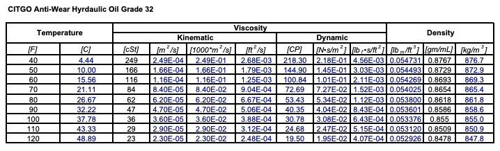
An example of a chart that shows the hydraulic oils’ viscosity range

The proper design method is to choose an oil that sits well in the components, especially the pump. The hydraulic power unit must be designed to maintain the operating temperature range desired to keep in this range. This often requires heat exchangers or immersion heaters in the oil, depending on the application and ambient temperature. Instead of a fixed displacement pump, a pressure-compensated pump will often help hold the fluid temperature at a relative constant.
The optimal way to control temperature and, therefore, viscosity is during the initial design phase. Choose the right components and design a system that can keep oil temperatures at a relative constant.
Atlantic Hydraulic Systems has a skilled team of engineers who are always happy to guide you through hydraulic system requirements and specifications and advise you on fluid suitability.